
FT-847 Modifications
![]()
General Coverage Mods
1. Disconnect all cables and connectors
from your radio.
2. Remove the carry handle by taking out the two screws at each end of the handle.
3. Remove the other two screws on the opposite side of the radio.
4. Remove the two screws from the rear of the radio.
5. Remove the remaining two screws from the bottom cover near the front panel.
6. Now you can remove the bottom cover from the radio.
7. Place the radioon a clean surface with the top face down.
8. Place the front pannel towards you.
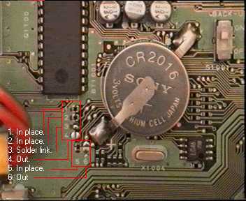
9. Now you should be able to see the lithium battery to the top left of the PCB.
10. Look closely and you will see 6 small surface mount resistors just bellow and to the left, They are labeled
on the PCB as 1,2,3,4,5,6 (see photo below).
11. You now need to configure the resistors as in the photo below.
12. After re-configuring double check your work and replace the covers.
13. Now reset the CPU as per handbook..
Notes from photo above
Receiver (the same as before modification)
| Band | Min RX Freq | Max RX Freq |
| HF | 100 KHz | 37 Mhz |
| VHF (a) | 37 MHz | 76 MHz |
| VHF (b) | 108 MHz | 174 MHz |
| UHF | 410 MHz | 512 MHz |
Transmitter
| Band | Min TX Freq | Max TX Freq |
| HF | 1.8 MHz | 32 Mhz |
| VHF (a) | 40 MHz | 76 MHz |
| VHF (b) | 137 MHz | 174 MHz |
| UHF | 410 MHz | 470 MHz |
Do Not under any circumstances transmit between 30Mhz and 36Mhz
as the low pass filter is active here and you could damage the PA strip on HF.
If you decide to carry out the same modification then you do so at your
own risk!
This modification verified to work on the following serial numbers.
8G060xxx --- 8I100xxx --- 8G051xxx